
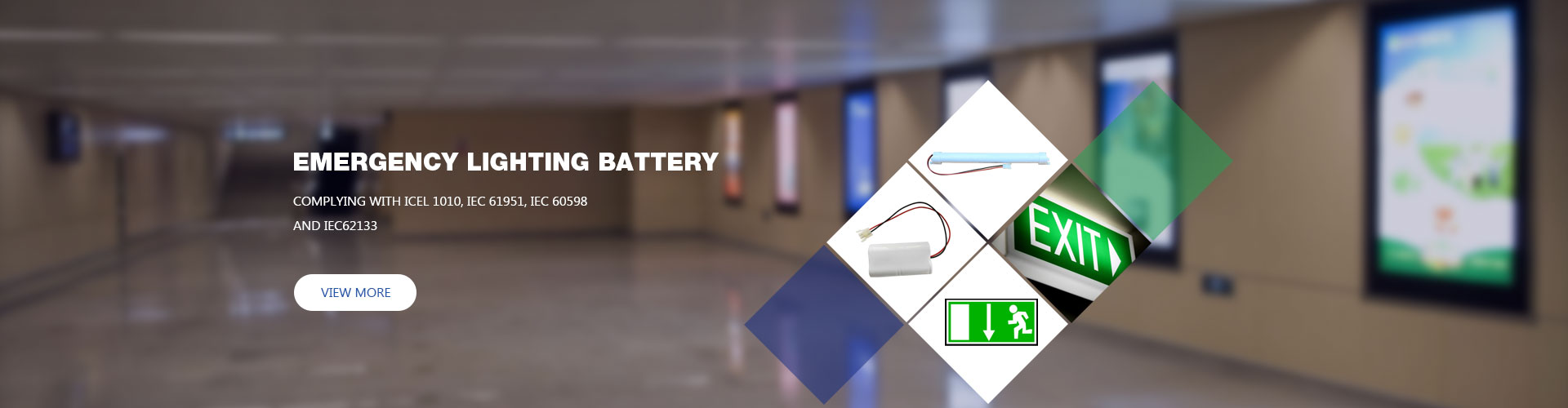


Emergency lighting batteries spend most of their operating life connected to mains power. They may be discharged only during functional tests, duration tests, or actual power failures, but the charging circuit remains active for thousands of hours.
This standby operating pattern makes charging control especially important. A nickel-metal hydride battery may tolerate a limited amount of overcharge, but continuously supplying more energy than the fully charged battery can safely absorb generates heat, increases internal pressure, accelerates material degradation, and gradually reduces available emergency operating time.
Panasonic defines overcharging as continued charging after a cell has reached a fully charged state and warns that charging a battery more than necessary can adversely affect its safety and electrical characteristics.
Preventing overcharging therefore does not simply mean disconnecting the battery at a fixed voltage. A reliable emergency lighting charger must control current, charging time, temperature, maintenance charging, and recovery after a discharge.
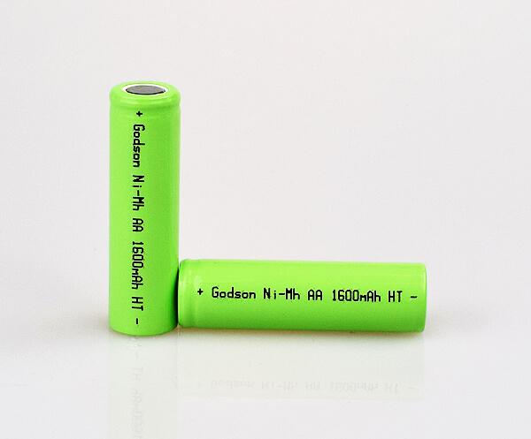
A portable Ni-MH battery may be charged, removed from its charger, and used until it needs charging again. An emergency lighting battery operates differently.
Under normal conditions, it is:
· Installed inside a luminaire or emergency conversion kit.
· Continuously connected to the charging circuit.
· Positioned close to an LED driver or other heat-producing components.
· Expected to remain ready for an unexpected power failure.
· Periodically discharged during required lighting tests.
· Recharged automatically when mains power returns.
This creates a difficult balance. The charger must replace energy lost through self-discharge and restore capacity after an emergency operation, but it must not keep applying a high recovery current after the pack is already full.
Ni-MH cells are included within the battery technologies used by emergency luminaires, while the current IEC 60598-2-22 edition specifies requirements for emergency lighting luminaires. Battery-supplied emergency lighting controlgear is also covered by IEC 61347-2-7.
1. Use Ni-MH Cells Designed for Emergency Lighting
Not every rechargeable Ni-MH cell is suitable for continuous standby charging.
Consumer AA cells, high-power tool batteries, button cells, and infrastructure-backup cells may all use Ni-MH chemistry, but they can have very different:
· Electrode designs.
· Charge-acceptance characteristics.
· Overcharge tolerance.
· Operating-temperature ranges.
· Self-discharge rates.
· Recommended maintenance currents.
· Expected service life.
Some Ni-MH products are designed for frequent cycling. Others are optimized for long-term backup duty and intermittent maintenance charging. The emergency lighting manufacturer must select the cell according to the actual standby environment rather than relying only on voltage and capacity.
Panasonic, for example, identifies dedicated infrastructure-backup Ni-MH batteries for emergency lights and similar standby applications, with product-specific operating-temperature and charging characteristics.
Before approving a battery, confirm:
· Exact cell series and manufacturer.
· Nominal and minimum capacity.
· Permitted continuous or intermittent charge current.
· Recharge conditions after full discharge.
· Maximum charging temperature.
· Expected life under the proposed charger design.
· Approved number of series-connected cells.
· Required safety and compliance documentation.
A battery should never be described as “suitable for emergency lighting” solely because it fits inside the luminaire.
2. Control Charging Current Accurately
Ni-MH emergency lighting batteries are generally charged using controlled current rather than a simple uncontrolled voltage source.
The charging current is commonly expressed as a fraction of battery capacity, known as the C-rate. For a 2,000 mAh pack:
· 0.1C corresponds to approximately 200 mA.
· 0.03C corresponds to approximately 60 mA.
· 0.01C corresponds to approximately 20 mA.
These examples explain the calculation only. They are not universal charging recommendations.
The correct current must come from the battery manufacturer’s datasheet. VARTA’s technical handbook, for example, gives different standard, accelerated, fast, and maintenance-charge values for different Ni-MH product families. It also states that suitable trickle current depends on the maximum permissible current, self-discharge losses, charging efficiency, temperature, and the required recovery time after full discharge.
The charger should maintain current within specification across:
· Mains-voltage variation.
· Component tolerances.
· Battery-voltage changes.
· Cold and hot operating conditions.
· Different production batches.
· End-of-life battery resistance changes.
A charger that provides an acceptable current at room temperature may overcharge the pack when component values drift or luminaire temperature rises.
3. Avoid Uncontrolled Continuous Trickle Charging
The term “trickle charging” is sometimes used as though all Ni-MH batteries can tolerate an indefinite low current. That assumption is unsafe.
Whether continuous trickle charging is acceptable depends entirely on the cell design. Some specialized Ni-MH cells permit it within a defined current and temperature range. Other Ni-MH cells should use intermittent charging instead.
VARTA describes maintenance-current ranges for particular button-cell families but also warns that life expectancy is reduced when a battery is continuously overcharged at the maximum permitted rate.
Panasonic likewise distinguishes specific high-temperature and infrastructure-backup cells from general-purpose Ni-MH products. Its handbook indicates that suitable intermittent charge control can improve longevity while reducing standby charging energy.
For long-term emergency lighting duty, intermittent charging can be preferable because it:
· Reduces the time during which charging current passes through a full battery.
· Limits continuous heat generation.
· Compensates for self-discharge without permanently applying recovery current.
· Can reduce charger energy consumption.
· Helps extend battery service life when properly matched to the cell.
A typical intermittent system applies short maintenance pulses separated by longer no-charge intervals. The exact pulse current, duration, and interval must be validated with the selected battery.
4. Use a Two-Stage Charging Algorithm
A two-stage charging system provides a practical balance between fast recovery and low standby stress.
Stage One: Controlled Recovery Charge
After a duration test or mains failure, the charger supplies the manufacturer-approved recovery current. Charging is controlled by one or more termination methods and a maximum safety timer.
Stage Two: Low-Level Maintenance
After recovery charging is complete, the circuit reduces the current substantially or changes to intermittent pulses. This stage only replaces losses caused by self-discharge.
VARTA describes an intermittent two-step method in which a time-controlled recharge follows a discharge, after which intermittent maintenance charging is used to cover self-discharge losses and stabilize available capacity.
The advantage is that the charger does not have to compromise between two conflicting requirements. Recovery can be completed within the required time without exposing a fully charged pack to the same current indefinitely.
5. Do Not Depend on a Single Charge-Termination Signal
Ni-MH charge termination is more complex than simply reaching one fixed voltage.
Battery voltage changes with:
· Charge current.
· Cell temperature.
· Battery age.
· State of charge.
· Cell construction.
· Number of cells in the pack.
For higher-rate charging, VARTA states that timer control alone is insufficient and recommends temperature-rate detection for appropriate cell families. Its guidance also describes negative-voltage detection and an additional temperature cutoff as backup protection.
A safer design might therefore use:
· Primary termination through temperature-rise or voltage behavior.
· A maximum time limit.
· An absolute pack-temperature cutoff.
· A current-limiting circuit.
· A fault state when sensor data is missing or implausible.
6. Monitor Battery Temperature Directly
Temperature is one of the clearest indicators of charging stress.
When a Ni-MH battery is approaching full charge, a greater percentage of the charging energy becomes heat. An abnormal temperature rise can indicate:
· Continued overcharge.
· Excessive charging current.
· An aged high-resistance cell.
· Incorrect charger operation.
· Poor ventilation.
· A shorted or damaged cell.
· Installation near an excessive heat source.
The temperature sensor should measure the battery pack itself, not merely the surrounding PCB. It should be:
· In close thermal contact with a representative cell.
· Electrically insulated where required.
· Protected against displacement during assembly.
· Positioned away from misleading local heat sources.
· Included in charger fault diagnostics.
A sensor located beside a warm LED driver may incorrectly report high battery temperature. Conversely, a sensor located too far from the cells may respond too slowly to an actual battery temperature rise.
The charger should also prevent or reduce charging outside the battery manufacturer’s permitted temperature range. Panasonic’s product specifications demonstrate that charging-temperature limits vary by Ni-MH model; for example, general-purpose and high-rate products may specify a defined charging range rather than unrestricted operation.
7. Improve Thermal Management Inside the Luminaire
Even a correctly programmed charger may overheat a battery when the luminaire has poor thermal design.
Emergency lighting batteries are frequently mounted close to:
· LED controlgear.
· Mains transformers.
· Charging resistors.
· Heat sinks.
· High-power LED modules.
· Enclosed ceiling spaces.
To reduce thermal stress:
· Separate the battery from the hottest electronic components.
· Avoid placing the pack directly above the LED driver.
· Provide sufficient internal airflow.
· Do not block luminaire ventilation openings.
· Reduce unnecessary heat generated by the charger.
· Validate battery temperature at the maximum rated ambient temperature.
· Test the luminaire in its intended installation orientation.
· Consider ceiling-cavity temperatures, not only room temperature.
The battery should be evaluated under worst-case conditions: fully enclosed luminaire, maximum mains voltage, maximum ambient temperature, full battery, and prolonged standby operation.
The current IEC 60598-2-22 edition includes clarified requirements related to high-temperature operation testing for emergency luminaires, reinforcing the importance of validating the complete luminaire rather than evaluating the battery in isolation.
8. Match the Charger to the Exact Battery Pack
Replacing a Ni-MH battery with a pack that has the same nominal voltage but different capacity does not guarantee compatibility.
A higher-capacity pack may require:
· A longer recharge time.
· A different recovery current.
· A different termination timer.
· Different temperature thresholds.
· A modified maintenance regime.
9. Use Matched Cells in Series-Connected Packs
Emergency lighting battery packs commonly contain multiple cells connected in series.
When one cell has lower capacity or higher internal resistance than the others, it may:
· Reach full charge earlier.
· Become hotter during continued charging.
· Reach its discharge limit earlier.
· Restrict the usable capacity of the entire pack.
· Experience greater electrical stress.
Pack manufacturers should therefore use cells with closely matched:
· Capacity.
· Open-circuit voltage.
· Internal resistance.
· Self-discharge behavior.
· Production history.
Replacing only one cell in an aged pack can create further imbalance. In most small emergency lighting packs, replacing the complete pack is more reliable than mixing a new cell with several aged cells.
VARTA also cautions against directly charging parallel-connected cells in its application guidance, recommending isolation measures when parallel charging cannot be avoided.
10. Provide a Maximum Safety Timer
Every emergency lighting Ni-MH charger should include a maximum charging-time limit.
The timer protects the battery when the primary termination system fails because of:
· A disconnected temperature sensor.
· Measurement noise.
· Firmware error.
· Damaged voltage-sensing components.
· An unusual initial state of charge.
· A battery that no longer displays a normal termination response.
The timer must be calculated using:
· Battery capacity.
· Charging current.
· Charge efficiency.
· Expected starting state.
· Temperature.
· Manufacturer requirements.
· Permitted production tolerances.
A timer should normally act as a backup, not the only fast-charge termination method. VARTA’s guidance explicitly states that timer-only control is insufficient for fast charging in the relevant Ni-MH product family.
11. Control Recharging After Emergency Lighting Tests
Full-duration tests create a deep battery discharge. Once mains power returns, the charger may remain in its recovery stage for several hours.
Repeated testing before recharge is complete can lead to:
· Insufficient capacity for the next emergency.
· Long periods at elevated charging current.
· Increased battery temperature.
· Difficulty distinguishing normal recovery from a charger fault.
· Unequal charging of cells within the pack.
Testing should therefore follow the applicable emergency lighting maintenance standard and provide adequate recovery time afterward.
IEC 62034 specifies performance and safety requirements for automatic testing systems used with battery-powered emergency escape lighting, including functional tests, duration tests, timing, component failures, and software failures.
An automatic-test system should ideally record:
· Date and duration of the test.
· Battery operating time.
· Recharge status.
· Battery or charger fault.
· Abnormal temperature.
· Failure to recover within the expected period.
12. Verify Charger Performance During Production
A correct schematic does not automatically guarantee a correct production charger.
Component tolerances, soldering defects, firmware versions, and substitute components can change actual charging performance. Production testing should therefore measure:
· Recovery charging current.
· Maintenance current or pulse duty cycle.
· Maximum timer operation.
· Temperature cutoff.
· Charger shutdown after sensor failure.
· Mains-voltage sensitivity.
· Charge indication.
· Reverse-polarity behavior.
· Battery disconnection response.
Testing only the open-circuit charger voltage is not enough. The circuit should be evaluated with a representative battery at several states of charge and at relevant temperatures.
A conceptual emergency lighting charging sequence may operate as follows:
1. Mains power returns.
The charger checks that the battery is connected and its temperature is within the approved charging range.
2. Battery condition is evaluated.
Pack voltage and recent emergency-operation data are used to determine whether recovery charging is necessary.
3. Controlled recovery current begins.
Current is limited to the value approved for the selected battery.
4. Voltage, time, and temperature are monitored.
Abnormal readings cause the charger to reduce current or enter a fault state.
5. Full-charge termination occurs.
The charger uses the selected primary algorithm with a maximum timer and absolute-temperature backup.
6. The circuit changes to maintenance mode.
Current is reduced or supplied intermittently to compensate for self-discharge.
7. Periodic maintenance checks continue.
The system monitors pack connection, temperature, charger current, and automatic-test results.
This is a control concept rather than a universal charger specification. Actual currents, thresholds, and timing must be obtained from the selected cell manufacturer.
Procurement Checklist for Ni-MH Emergency Lighting Batteries
For OEM projects or bulk battery purchasing, request the following information from the supplier:
· Cell model and original manufacturer.
· Minimum and typical capacity.
· Permitted standard-charge current and duration.
· Accelerated or recovery-charge specifications.
· Permitted continuous maintenance current.
· Recommended intermittent-charge profile.
· Charging-temperature range.
· Overcharge-test conditions.
· Expected life under emergency lighting standby conditions.
· Cell matching and pack-assembly process.
· Temperature-sensor options.
· Connector, lead length, and polarity drawing.
· Production date and traceability code.
· Applicable IEC, safety, and environmental documentation.
· Sample-pack validation before mass production.
Statements such as “five-year battery,” “high-temperature battery,” or “overcharge resistant” should be supported by clearly defined charging current, temperature, discharge frequency, and end-of-life conditions.
Preventing overcharging in emergency lighting Ni-MH batteries requires more than adding a charging resistor or setting a fixed voltage limit.
The charger must distinguish between recovery charging and long-term maintenance. It should supply an accurately controlled current, terminate recovery charging through appropriate time, voltage, and temperature controls, and then change to a manufacturer-approved low-current or intermittent maintenance mode.
Reliable overcharge prevention also depends on selecting infrastructure-grade Ni-MH cells, controlling luminaire temperature, matching the battery to the charger, using well-matched cells, validating production units, and monitoring performance during functional and duration tests.
When the battery pack, charging circuit, thermal design, and emergency lighting control system are developed together, manufacturers can reduce premature battery failures while maintaining the emergency operating time required for safe building evacuation.


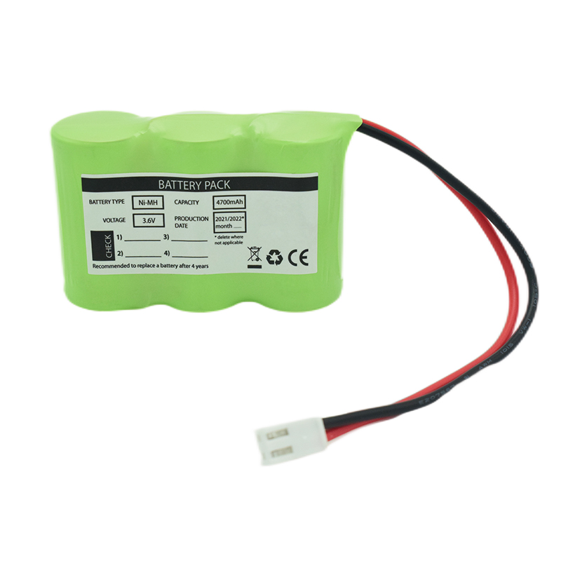 Ni-MH Battery C4700mAh 3.6V
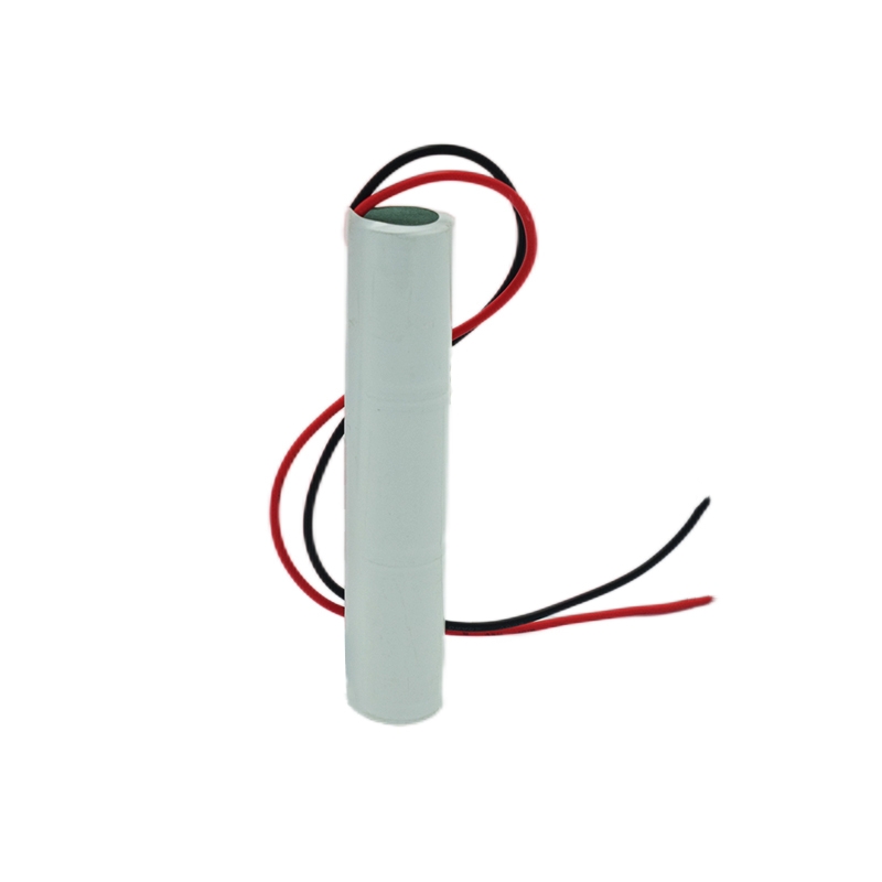 Nickel Cadmium Nicd Battery Pack SC1800mAh 3.6V
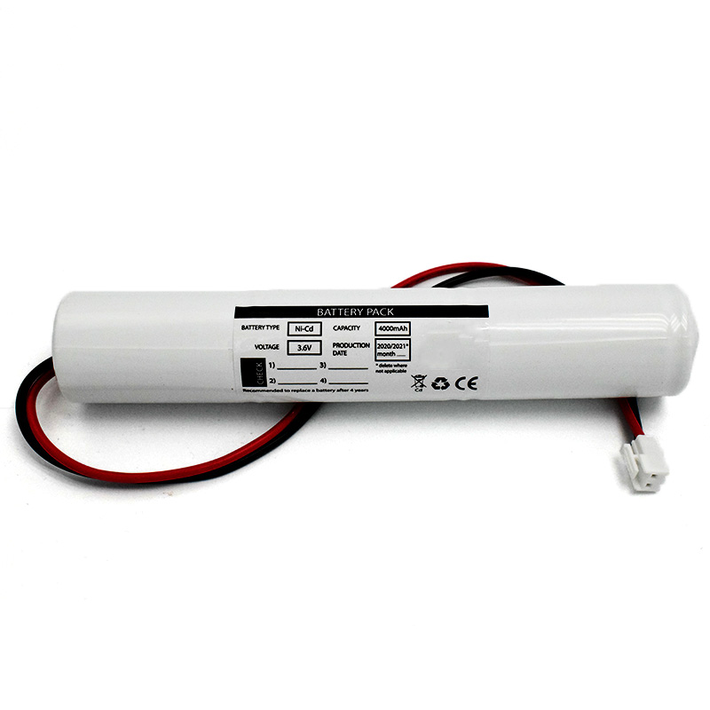 Ni-Cd Battery Pack D4000mAh 3.6V
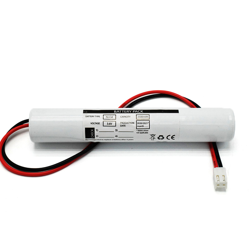 Ni-Cd Battery Pack C2500mAh 3.6V
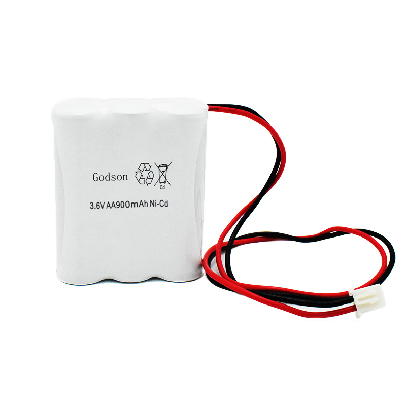 NICAD Battery Pack AA900mAh 3.6V
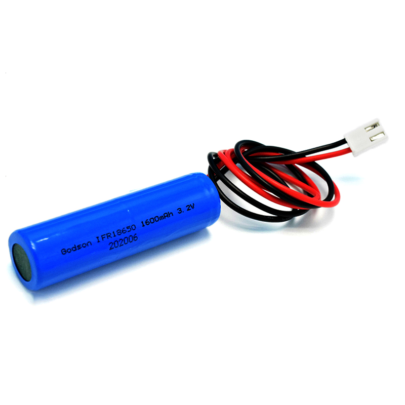 LiFePO4 IFR18650 1600mAh 3.2V
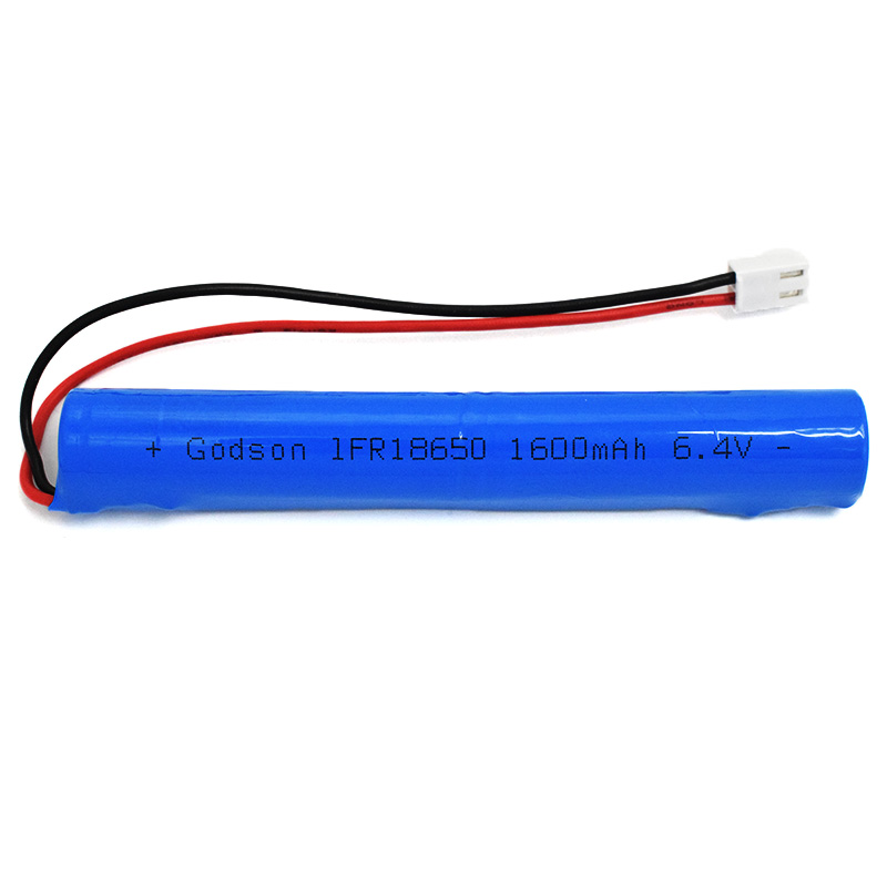 LiFePO4 IFR18650 1600mAh 6.4V
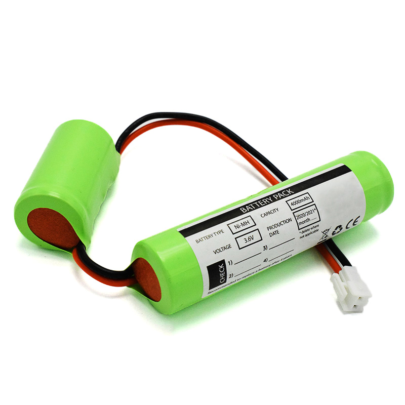 Ni-MH Battery C4000mAh 3.6V
 E-bike Battery 48V 10Ah JL-1
 E-bike battery 48V 10Ah Qing Tian